FAQs
What is Power over Ethernet (PoE)?
Power over Ethernet, often abbreviated to PoE, is the name given to a series of standards which safely pass both data and electrical power on a twisted pair Ethernet cable. PoE paved the way for devices such as Voice over Internet Protocol (VoIP) phones, Internet Protocol (IP) cameras, Point of Sale (PoS) systems, Door Access Controllers & Wireless Access Points (WAP’s).
What is Power Sourcing Equipment (PSE) & a Powered Device (PD)?
In all implementations of PoE, which will be outlined in further detail below (Mode A, Mode B & 4PPoE), the IEEE standards provide signalling protocols between Power Sourcing Equipment (PSE) and a Powered Device (PD). These protocols allow a PoE compliant device to be detected by the power source and negotiate directly with it, both the amount of power available and the power required.
All PoE standards follow the same convention when identifying a PSE or a PD, as outlined below:
- Power Sourcing Equipment (PSE) is a PoE device which is capable of delivering power over Ethernet to an external device. This could be a PoE Injector, a PoE Splitter or a PoE switch, such as the Brainboxes SW-525
- A Powered Device (PD) is an external PoE device which accepts power from a PSE over Ethernet. This can be any number of devices, such as a Brainboxes Ethernet to Serial Converter (ES-420 or ES-446), a VoIP phone, CCTV cameras or a PoS system.
The term “PoE Capable” is also frequently used when describing PoE, and can be used to reference either a PSE or a PD, sometimes both.
What is the “Power Budget”?
Measured in Watts, the PoE “Budget” of a PSE is the total amount of power that can be delivered to connected PD’s at a single time. As an example, consider the Brainboxes SW-525 power budget. This is 90W maximum, deliverable to PoE, PoE+ or a mixture of devices using either standard.
The SW-525 features four PoE capable RJ45 ports. Each of these ports is compliant to the IEEE 802.3at standard, meaning each port could deliver a theoretical 30W of power. This would equate to a total usage between the four ports of 120W.
As outlined above, the maximum power budget available on the SW-525 is 90W, 30W less than the theoretical 120W output of the four ports. This means that each of the PoE ports available is capable of delivering up to 30W to a connect PD, provided that the total power budget isn’t exceeded. Connecting PD’s such that the power budget is exceeded could see devices partially or inconsistently operate.
PoE Standards & Power Capabilities
Under the 802.3 group of standards collated by the Institute of Electrical and Electronics Engineers (IEEE), are defined standards for PoE, PoE+ & PoE++. Each has a specification detailed, outlying the power requirements that a PSE must be able to deliver to a PD.
The earliest standard for PoE, 802.3af-2003, paved the way for PoE technology. Requiring an input voltage of between +44VDC and +57VDC, a maximum of 15.40W (Type 1) could be delivered by a PSE. Of the deliverable 15.40W, a maximum of 12.95W is guaranteed to be available at the PD. The loss in wattage is due to dissipation along the cable run.
An updated standard, 802.3at-2009, expanded on the technologies of PoE further and was designated PoE+ or “PoE Plus”. The new standard almost doubled the available power that could be delivered by a PSE. With a deliverable wattage of 30W (Type 2), compared to the 15.40W of previous standard, a guaranteed wattage of 25.5W could now be achieved at the PD interface. This increased wattage also came with an increased input voltage requirement of +50VDC to +57VDC.
An increased power budget wasn’t the only improvement on the original PoE standard. The 802.3at (PoE+) also allowed backward compatibility with PoE PD’s designed for the 802.3af (PoE) standard. PSE’s will intelligently detect the standard a PD complies to, restricting power to them accordingly. It is however worth noting that while this is the case, a PSE operating under the 802.3af standard cannot provide enough power to supply a PD operating under the 802.3at standard.
As well as detecting the standard of a PD, 802.3at would also allow intelligent budgeting of power between the PSE and connected PD’s, negotiating between themselves an allowance of power for each connected PD from the overall budget of the PSE.
The further expanded 802.3bt-2018 standard, again brought new power capabilities, increased again beyond those available in the 802.3at standard. This new standard is also referred to as PoE++ or 4PPoE. Two more power types were defined under the new standard; Type 3 allows for a deliverable 60W, of which 51W could be guaranteed at the PD interface, while Type 4 allows for a deliverable 100W, with a guaranteed 71W at the PD interface.
An increased input voltage was now also required. Type 3 PSE’s required +50VDC to +57VDC as with Type 2 PSE’s, however, Type 4 PSE’s required a slight increase of +52VDC to +57VDC. In addition to the higher input voltage requirements, a higher current rating was also needed for the increased load, at 600mA & 960mA (per twisted pair) for Type 3 & Type 4 respectively.
The standardisation and implementation of PoE++ enabled a new array of PoE applications with both an increased deliverable power and Ethernet transmission speeds up to 10Gbps.
PoE Standard Parameters
| 802.3af (Type 1) PoE |
802.3at (Type 2) PoE+ |
802.3bt (Type 3) PoE++ |
802.3bt (Type 4) PoE++ |
|
|---|---|---|---|---|
| Maximum Power Delivered by PSE | 15.40W | 30W | 60W | 100W |
| Maximum Power Available at PD | 12.95W | 25.5W | 51W | 71W |
| Voltage Range at PSE | +44VDC to +57VDC |
+50VDC to +57VDC | +50VDC to +57VDC | +52VDC to +57VDC |
| Voltage Range at PD | +37VDC to +57VDC |
+42.5VDC to +57VDC | +42.5VDC to +57VDC | +41.1VDC to +57VDC |
| Maximum Cable Current (Per Pair) | 350mA | 600mA | 600mA | 960mA |
| Supported Modes | Mode A (Endspan) & Mode B (Midspan) | Mode A & Mode B | Mode A, Mode B & 4-Pair Mode | 4-Pair Mode Compulsory |
Mode A, Mode B or 4-Pair?
There are numerous implementations of transmitting power over Ethernet cables, three of which were standardised by the IEEE, under the 802.3 group of standards. Each of these implementations are known as:
- Mode A (Also referred to as Alternative A)
- Mode B (Also referred to as Alternative B)
- 4PPoE (Also referred to as PoE++)
In Mode A, only two of the four available signal pairs are utilised, both data and power being passed along the same two signal pairs of a conventional CAT5 cable. This is possible by applying a common mode voltage onto each of the pairs, which, because Ethernet uses differential signalling, doesn’t impede the data transmission. This applies to 10Mbit/s & 100Mbit/s Ethernet speeds.
In Mode B, all four of the signal pairs in a conventional CAT5 cable are utilised, with data and power separated onto different differential pairs. Two of the pairs are used for data and the other two pairs are used for power.
A PSE which delivers power and data on the same differential pairs (Mode A), is also generally referred to as an “Endspan” PSE. One which delivers power and data on separate differential pairs (Mode B), is also generally referred to as a “Midspan” PSE.
With Gigabit Ethernet, both Mode A & Mode B implementations support power over the same differential pairs used for data, this being as Gigabit Ethernet uses all four differential pairs for data transmission, allowing up to 1Gbps transmission speeds.
4PPoE or 4-Pair PoE, is designed for high powered applications, supplying power and data over all four differential pairs. This is most commonly in CCTV applications for Pan-Tilt-Zoom (PTZ) cameras due to the requirement of high power and high data throughput, but can also be used in other deployment such as charging laptop batteries.
Special considerations must be taken into account when using 4PPoE due to the increased power capabilities supported, namely ensuring that the correctly specified cable is used.
| Mode A | Mode B | 4-Pair | ||||
|---|---|---|---|---|---|---|
| Pin | Data | Power | Data | Power | Data | Power |
| 1 | Tx+ | DC+ | Tx+ | BI_DA+ | DC+ | |
| 2 | Tx- | DC+ | Tx- | BI_DA- | DC+ | |
| 3 | Rx+ | DC- | Rx+ | BI_DB+ | DC- | |
| 4 | DC+ | BI_DC+ | DC+ | |||
| 5 | DC+ | BI_DC- | DC+ | |||
| 6 | Rx- | DC- | Rx- | BI_DB- | DC- | |
| 7 | DC- | BI_DD+ | DC- | |||
| 8 | DC- | BI_DD- | DC- | |||
| Key: | Tx = Transmit +/- | Rx =Receive +/- | BI_D = Bidirectional +/- | |||
Is my PoE device Compliant or Compatible?
Not all Power Sourcing Equipment (PSE’s) or Powered Devices (PD’s) are compliant with the IEEE 802.3 PoE standards, but they may still work. All Brainboxes PSE’s and PD’s are fully compliant to the IEEE 802.3af (PoE) & 802.3at (PoE+) standards.
A “Compliant” PSE must support Mode A, Mode B or both methods of power delivery. Equally, a “Compliant” PD must accept both Mode A & Mode B methods of power delivery.
A “Compatible” PSE & PD do not adhere to the above standardisation, may use non-standard voltages, lack PoE negotiation or support vendor-specific pinouts, making them compatible rather than compliant.
Can I use a Non-PoE device with PoE capable devices?
Yes; not every device is natively PoE capable, meaning that it cannot accept power directly over Ethernet. In such situations, there are numerous methods of implementing PoE onto your network in a range of configurations to overcome this.
How can I deploy PoE onto my network?
Implementing PoE onto a network, is typically achieved using a dedicated PoE switch (PSE) which delivers power to a Powered Device (PD) directly. However, this isn’t always the case, sometimes you may find a switch isn’t PoE compatible, or the number of PoE devices doesn’t warrant the purchase of a dedicated PoE switch for an overwhelmingly non-PoE network.
In this case, there are a number of PoE accessories available which can support the use of PoE devices in these cases:
| Key | |
|---|---|
| PoE & Data | Black (Solid Line) |
| Power Only |
Blue (Dashed Line) |
| Data Only |
Red (Dotted Line) |
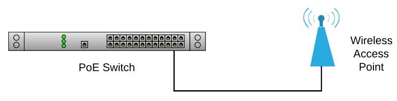
PoE Switch to PoE Device
Arguably the simplest implementation of PoE, is using a PSE to power a PD through a direct Ethernet cable. As shown in the diagram below, a PoE switch is connected directly to a PoE Wireless Access Point (WAP), delivering power and data over a single cable:
Non-PoE Switch to PoE Device
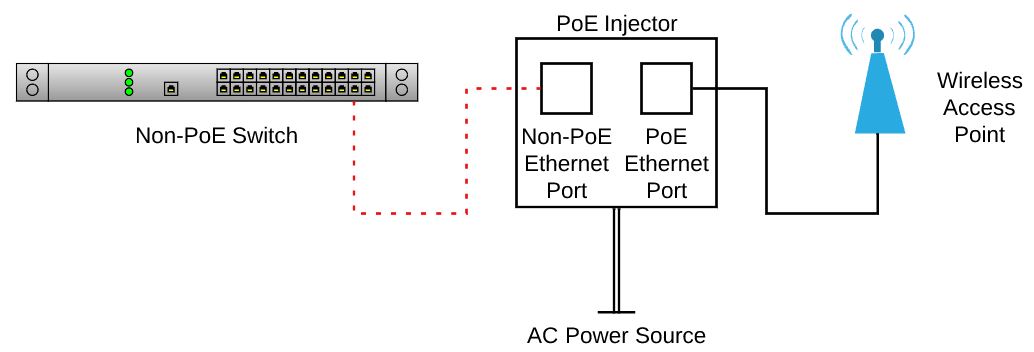
How do you deliver power to a PD over an existing network which doesn’t have any PoE capability? As aforementioned, there are a number of PoE accessories available for PoE implementation. One of these accessories is a PoE Injector.
The PoE Injector acts as an intermediary device between a non-PoE network connection, such as a non-PoE switch and a PoE device. Featuring a pair of Ethernet ports, it is vital to both understand and identify the differences between these Ethernet ports prior to making any connections.
The first Ethernet port is a non-PoE port and should always be connected to the non-PoE device. The second Ethernet port is PoE capable and is to be connected into the PoE device. As shown in the diagram below, the connection between the non-PoE switch and non-PoE port of the injector is only capable of data transfer. The PoE port on the other hand is capable of providing both power and data between the PD device, in this case a Wireless Access Point (WAP) and the injector.
Internally, the injector can transfer data between each of the ports allowing the switch and access point to communicate with each other. It should also be noted that a PoE Injector requires an external AC power source in order to operate:
PoE Switch to Non-PoE Device
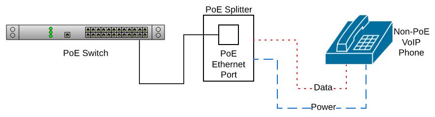
Now lets consider a PoE capable switch installed on a network, however, a new PD being connected isn’t PoE capable. Opposite to an Injector, a PoE Splitter is another PoE accessory which acts as an intermediary, this time between a PoE PSE and a non-PoE PD.
A splitter features a single PoE capable Ethernet port, which accepts data and power from a PoE PSE, in this case the switch. It’s main function is to, as the name suggests, split the power and data from the PoE port into two separate cables. Each of the cables is typically only around 5 to 10 centimetres in length, one is terminated into a power jack and the other into a Non-PoE Ethernet connector.
Since the source of the power for the non-PoE PD has been split from the incoming PoE cable, this negates the requirement for an external AC power source.
Depending on the mode of splitter, the terminations of the power and data cable may vary. Typically, these are found with a 4mm jack adaptor for the power and an RJ45 connector for the data, such as the Brainboxes PW-323.
In the example below, a PoE switch is connected to a non-PoE VoIP phone using a splitter:
Non-PoE Switch to Non-PoE Device
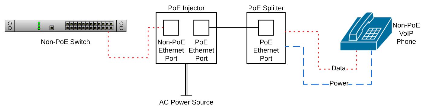
The final implementation of PoE on a network, applies when connecting a non-PoE PSE to a non-PoE PD. This can be implemented when long cable runs may be required, or when AC power isn’t readily available. In this scenario, both a PoE Injector and PoE Splitter would be used.
As can be seen in the diagram below, a non-PoE switch is connected through both an injector and splitter before connecting into a non-PoE VoIP phone. First, lets consider the connection between the switch and the injector; as the cable only needs to transmit data, the two can be located close together or over a distance, up to the Ethernet standard maximum, 100 meters.
If we next consider the connection between the PoE splitter and the VoIP phone. Typically, the splitter would be located within close proximity to the PD, given the short cable lengths of of the splitter’s data and power cable.
Lastly, is the connection between the PoE injector and PoE splitter. These could again be located within close proximity to each other, or extended across an Ethernet cable up to the maximum range of 100 meters. A consideration should always be made when running the cable between the injector and splitter over a greater distance, this is due to the power loss sustains across the cable from heat, as described earlier:
In summary, PoE has evolved considerably since from the original standard in 2003, to the updated standard of 2018. With numerous devices and implementation methods becoming available, it has pioneered a method of more efficient and cost effective network deployment.
FAQs