FAQs
What is the PE-205?
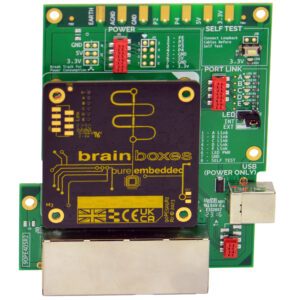
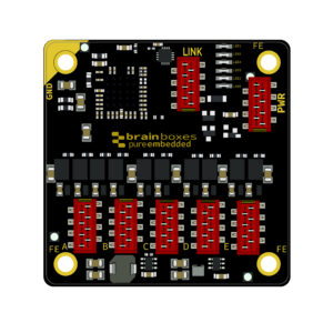
The PE-205 is a compact industrial DC-DC power supply module from Brainboxes’ Pure Embedded (PE) range.
It converts a +5 V to +30 V DC input to a +3.3 V DC output and is designed to provide clean, reliable power for PE switches and other low-voltage embedded devices.
With its 4 W output, reverse-polarity protection, and digital power control, it’s ideal for space-constrained or modular designs.
Who is the PE-205 designed for?
The PE-205 is designed for users of Brainboxes PE modules who want a compact, reliable, and convenient way to power PE switches or other low-voltage embedded devices. The PE-205 features a PE modular stacking system, which allows direct power delivery to other PE modules, perfect for compact or enclosed setups where space is limited.
Please be aware that the PE-205 cannot be stacked with the PE-508.
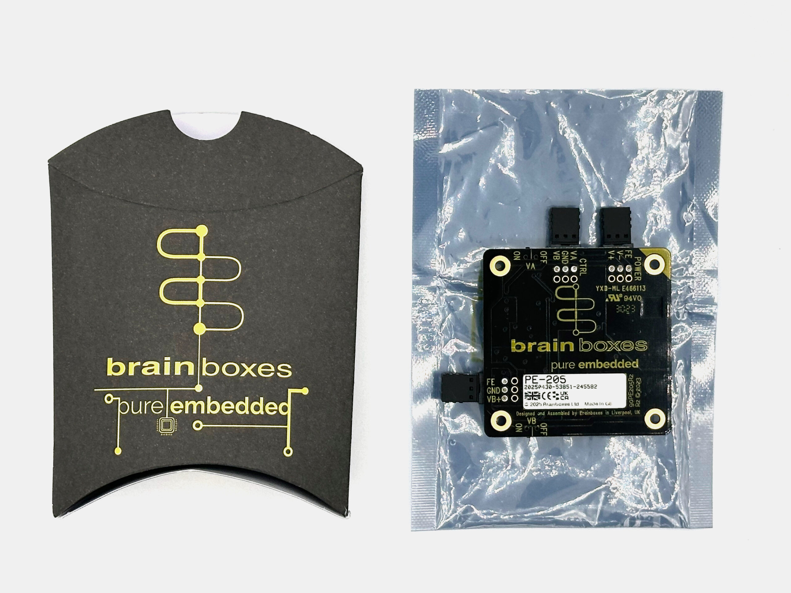
What’s included in the box?
When you receive your device, it will come in our Brainboxes pillow box.
Inside, you’ll find:
- 1 × PE-205 (in anti-static packaging)
- 1 × product information label (with serial number)
Please keep a record of the serial number for the future for reference to your device and if needed by the support team.
You can access our downloadable 2D & 3D designs here.
Key Features
| Wide input range: +5 V to +30 V DC |
| Dual controllable 3.3 V outputs: VA & VB channels |
| Digital on/off control for remote operation |
| Short-circuit & reverse-polarity protection |
| Compact size: 55 mm × 55 mm (smaller than a business card) |
| Stackable design with PE-505 & PE-515 Ethernet switches |
| Guaranteed availability until at least 2035 |
How do I set up the PE-205?
Use the PE-205 datasheet as your main reference. It includes:
- Wiring diagrams
- Input requirements
- Pin configurations
- Connection and output details
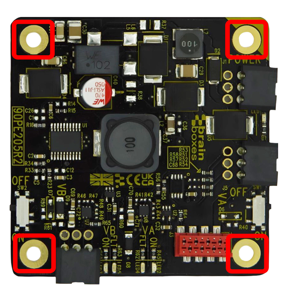
1. Mount the Device
Use 4 × M3 screws to secure the module.
Ensure at least 20 mm clearance above the board.
If your system does not share ground, use non-conductive standoffs.
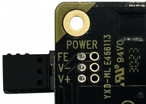
2. Connect Power Input
Supply +5 V – +30 V DC via the 3-pin power input connector.
Observe correct polarity:
FE = functional earth
–VIN = ground
+VIN = positive supply
3. Connect Outputs
VA & VB outputs both supply +3.3 V DC.
Use either or both outputs to power PE modules or other 3.3 V devices.
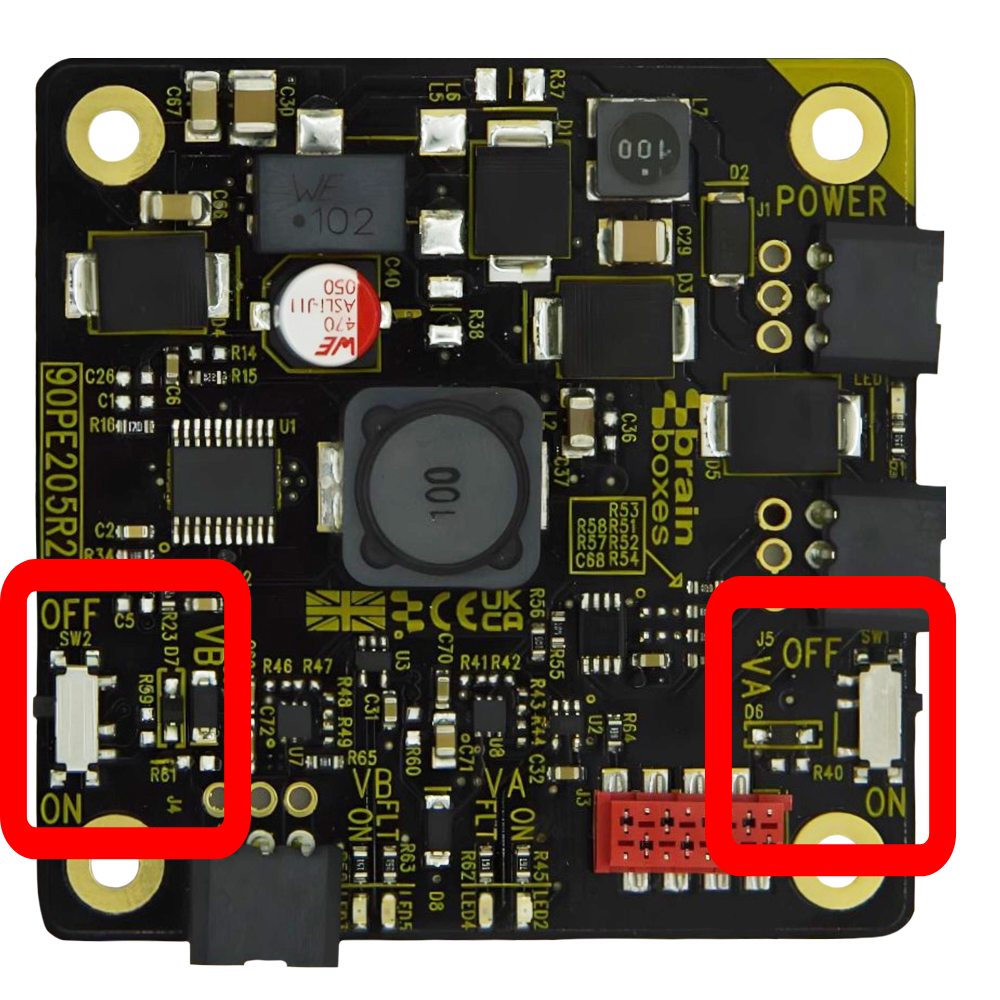
4. Enable Power Output
Each output can be toggled:
Physically: via onboard logic switches
Remotely: via Digital Control pins (VACTL / VBCTL)
Configure logic mode:
NPN: Power on when signal pulled Low
PNP: Power on when signal driven High
5. Verify Operation
|
LED States: |
|
| Green Power LED: | Input power OK |
| Green VA/VB LEDs: | Output enabled |
| Red LED: | Fault detected |
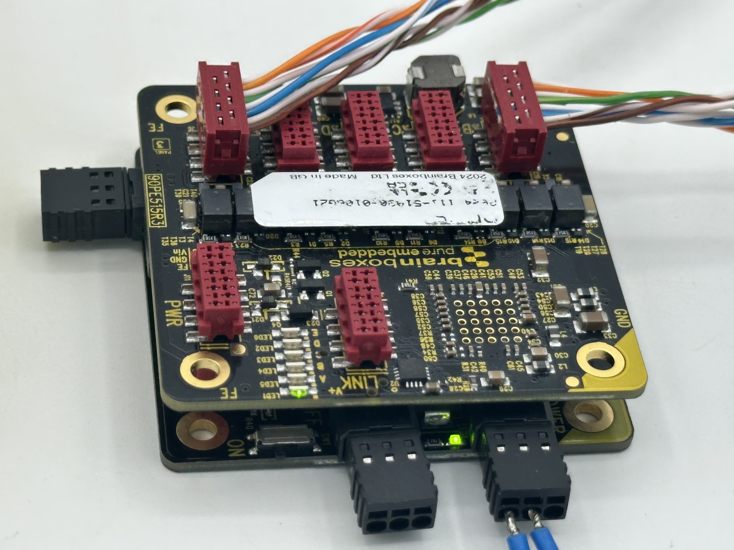
How do I use the modular stacking feature?
The PE-205’s main feature is modular stacking, which allows it to power the various Brainboxes Pure Embedded range by simply mounting the device on the PE-205. A simple and wire-free way to power your Pure Embedded devices.
The PE-205 is designed to stack directly with:
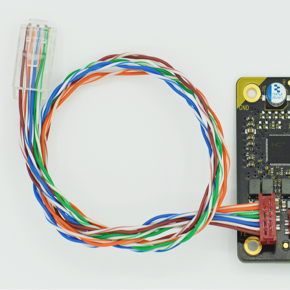
The connection uses an 8-way IDC header (TE 338728-8), which allows the PE-205 to power the switch directly, eliminating the need for additional cabling.
The PE-508 does not support modular stacking.
Can I power non-stacking modules?
Yes! You can use the VB power output to power devices that do not support modular stacking, such as the PE-508.
- Prepare two wires by stripping and connecting them to the PE-205 VB output (GND and V+) and the PE-508 power input.
- When you power on the PE-205, the LED on the PE-508 should light up.
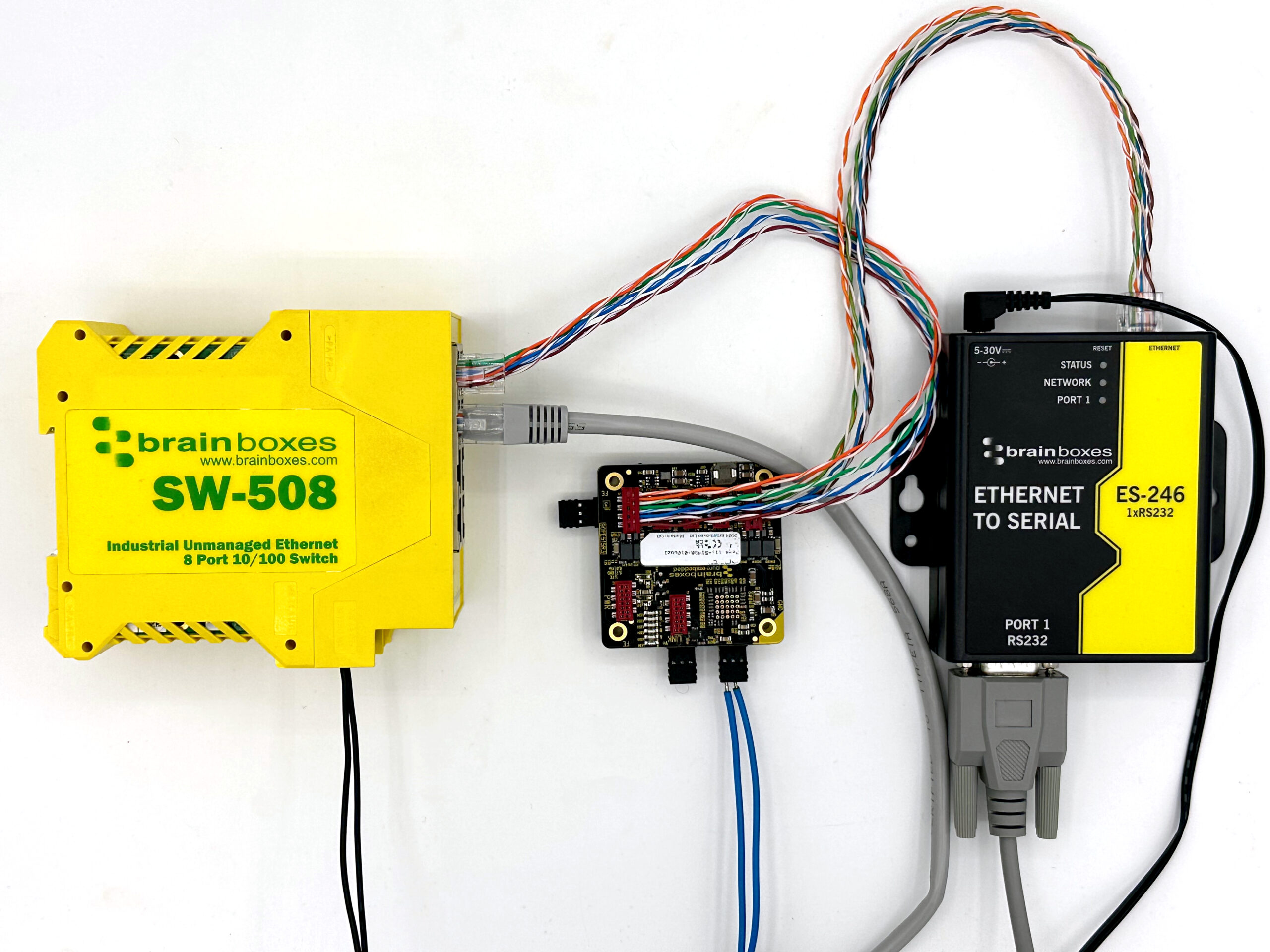
Can the PE-205 power and network multiple modules?
Yes! The PE-205 can power multiple Pure Embedded modules simultaneously and support network communication.
The example test setup below demonstrates how to use the PE-205 to power the PE-515. In this configuration, the PE-515 serves as a network switch, allowing you to connect and communicate with an ES device.
Example test setup:
- Connect an IDC-to-Ethernet connector to one of the PE-515’s LAN ports.
- Connect the PE-515 to your network. (In this example, the PE-515 was linked to the local area network via the SW-508.)
- The RJ45 and status LEDs on the PE-515 should blink, indicating network activity.
- Connect an ES-246 to another LAN port on the PE-515 via an IDC-to-Ethernet connector.
- After a few seconds, the ES-246’s network LED will start blinking.
- Test connectivity by connecting to the ES-246 via Boost.LAN or a web browser.
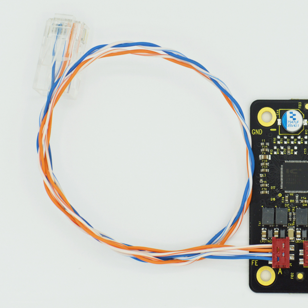
As shown in the example image above, we offer an IDC-MM to RJ-45 network cable specifically for the PE-505, PE-508, and PE-515 models.
These are supplied in packs of five, giving you a convenient jump-start to working with the PE Series.
CC-500: https://www.brainboxes.com/product/accessories/cc-500
CC-510: https://www.brainboxes.com/product/accessories/cc-510
-
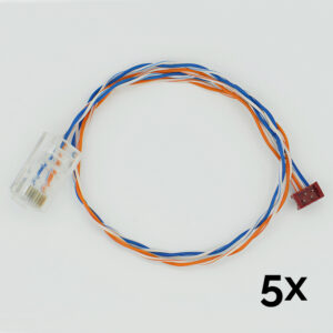
CC-500
$13.50 Add to cart -
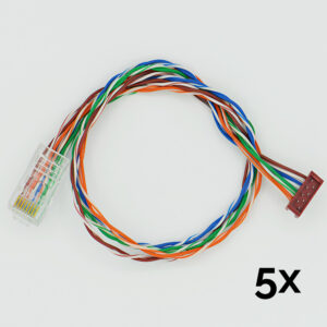
CC-510
$16.88 Add to cart -
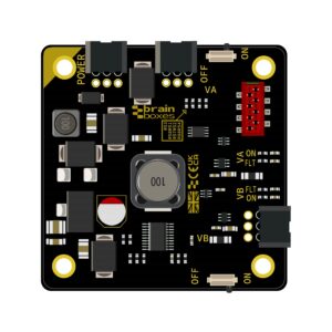
PE-205
$47.25 Add to cart -
PE-405
$202.50 Add to cart -
PE-415
$202.50 Add to cart -
PE-505
$47.25 Add to cart -
PE-508
$60.75 Add to cart -
PE-515
$74.25 Add to cart
FAQs