FAQs
How to find your ED device on the network?
The ED-582 and ED-593 are set to obtain an IP address from a DHCP server on its Ethernet network.
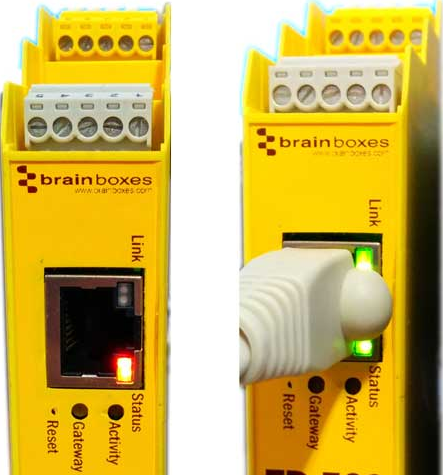
Connecting an ethernet cable
Connecting an Ethernet cable to your device will show that the device is connected to the network. There are two LEDs on the device. If the LEDs are blinking green, then the device has been assigned an IP address. If the LED is only blinking red, an IP address has not been assigned to the device.
Boost.IO Manager
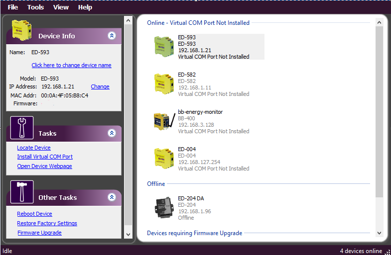
The IP address of the ED device can be found using the Boost.IO manager application, which in turn can be copied to a web browser to access the ED’s web page. Opening this application allows you to find your device on the network. Once opened, press F5 or click the find devices button. From here you can view any ED devices that are connected to the network.
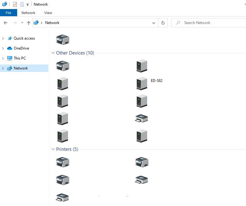
UPnP
This feature allows you to view the ED devices in the windows network tab.
How to configure the device on the webpage?
Upon entering the webpage you will be taken directly to the “Home” page. The menu on the left-hand side is used to navigate through the application.
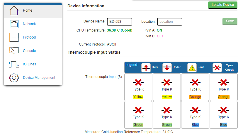
The ED-582 supports up to 4 RTD inputs, whereas the ED-593 supports up to 8 thermocouple inputs.
1. Temperature Unit
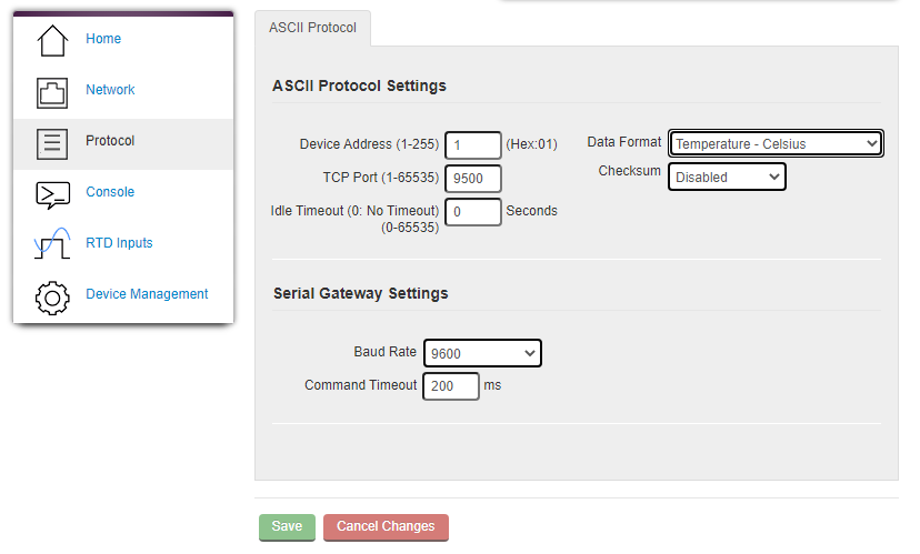
On the left side menu, there is an option called “protocol”. This option allows the temperature scale to be changed (the temperature is automatically set to Celsius unless changed). “Data Format” has a drop-down menu that will give a list of available temperature formats.
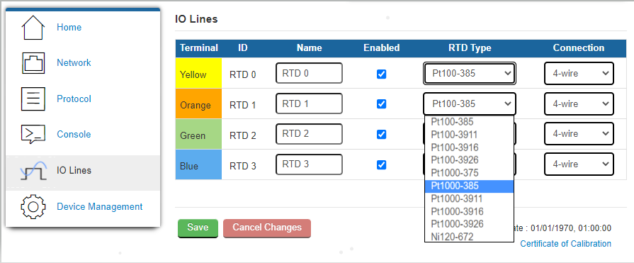
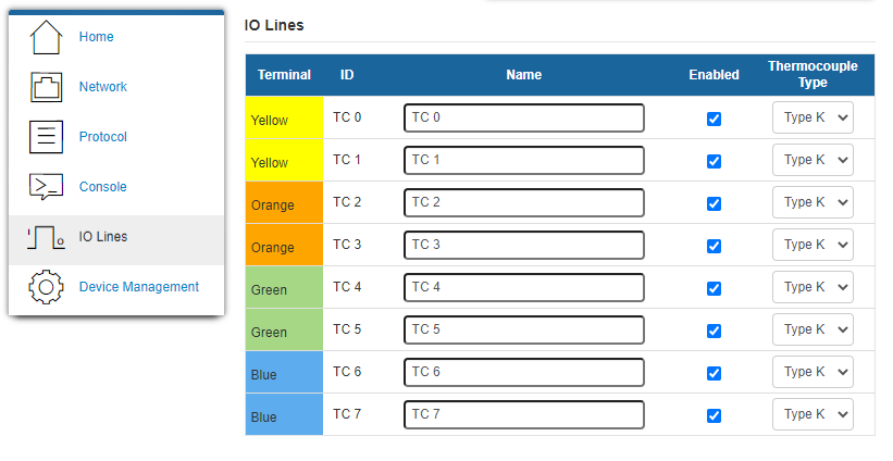
Next, On the side menu, there will be an option for RTD/Thermocouple Inputs.
2. Channel Name
This can be set to a custom name to where, or what it is being used for. e.g. “Fridge1”.
3. Enabled Status
Enabled must be ticked if the RTD/Thermocouple is integral to its function.
4. RTD Type and Number of connection wires
On the ED-582, connection relates to how many wires your RTD has. This would need to be selected to the right amount (2, 3 or 4).
The RTD type would be selected for setting the resistance coefficient.
5. Thermocouple Type
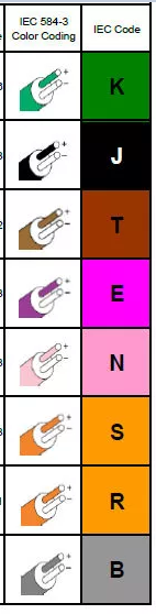
On the ED-593, we can set the thermocouple type on the Thermocouple Inputs page. The ED-593 supports the following thermocouple types K, J, T, E, R, S, B and N.
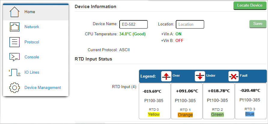
How to view temperatures on the webpage?
Whilst on the webpage and assuming temperatures have been set, the home page will display the temperatures of each RTD or Thermocouple that has been set.
How to read temperature using ASCII protocol?
The Brainboxes’ ASCII protocol can be accessed via the webpage, TCP socket connection, or via a virtual COM port.
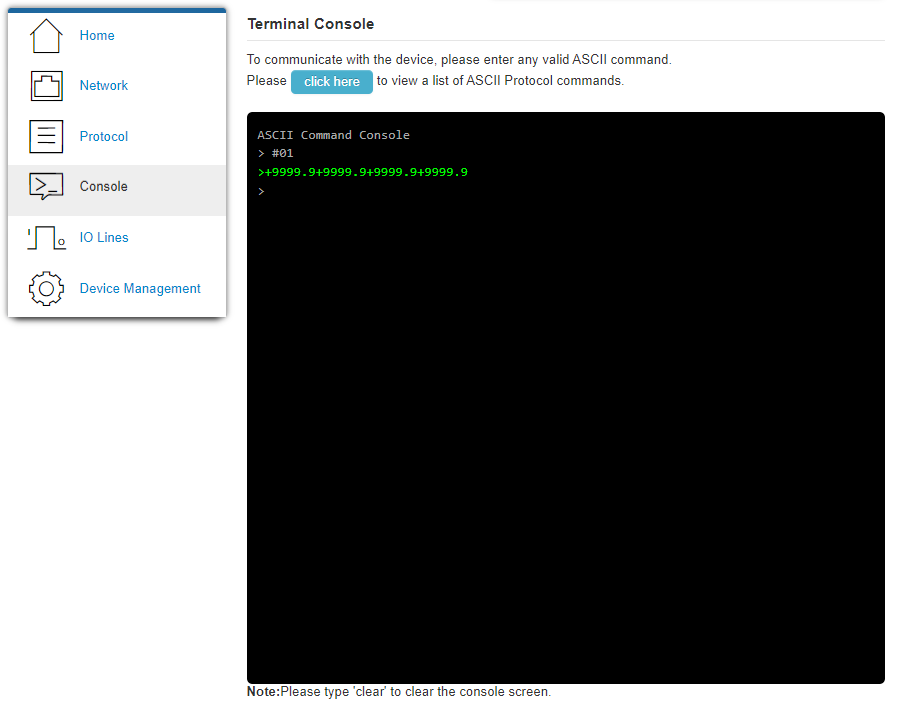
Temperature readings may also be viewed using the ASCII protocol. To access the ASCII protocol on the webpage, from the side menu, select “console”. This brings up the terminal console. Type “#01” into the command console and press enter. This will return with the temperature in whichever measurement unit has been selected.
To view the full list of available ASCII commands that can be entered into the console, press the “click here” button.
How to read temperature using Modbus protocol?
ED-582 and ED-593 do not support the Modbus protocol currently.
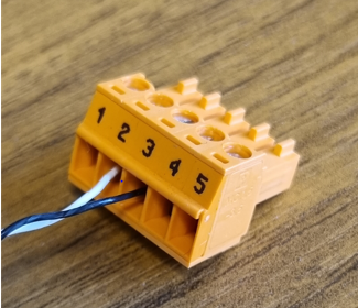
How to wire an RTD to an ED-582?
On the ED-582, each input has a colour and code attached to them. Each terminal pin is numbered for ease.
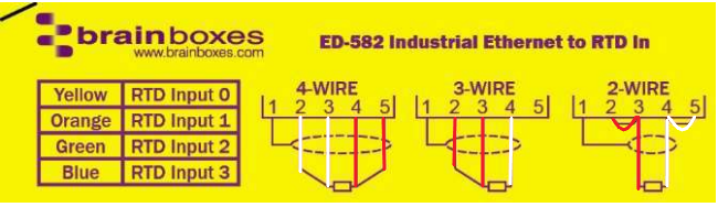
Please note that the black terminal is the input power terminal.
These codes/colours, make it easier to monitor which ones you have set up. The wires should be input into the terminal as specified below.
Wiring a 4-wire RTD
A 4-wire RTD will typically consist of 2 white wires and 2 red wires. First, one white wire will go into terminal pin 2. The second white wire into terminal pin 3.
Next, the two red wires will go into pins 4 and 5.
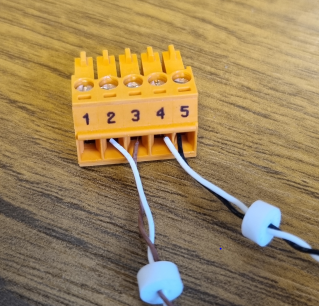
Wiring a 3-wire RTD
A 3-wire RTD will usually consist of 1 white and 2 red wires. In this case, the two red wires will go into pin 2 and 3. The white wire will go into pin 4.
Wiring a 2-wire RTD
These will consist of 1 white and 1 red wire. The red wire will go into pin 3 with a shorting link into pin 2. The white wire should then be put into pin 4 with a shorting link into pin 5.
NOTE: Some RTDs may include an earth sheath wire. If this is the case then wire it to pin 1.
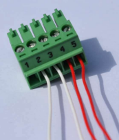
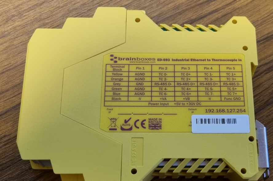
How to wire a thermocouple to an ED-593?
The thermocouple will consist of two wires. This will usually be a white wire (-) and the second wire (+), the colour will depend on the type of thermocouple being used. The ED-593 supports eight different types of thermocouples (K, J, T, E, R, S, B and N). Each type will correspond to a colour (shown in the image below). Which one you use will depend on the range of temperatures you want to measure.
The ED-593 is colour-coded for each terminal and numbered for each pin. To wire the thermocouple, any terminal may be used, other than the black and grey terminals. When wiring the thermocouple make sure that the white wire (-) is always placed in a lower-numbered pin than the coloured wire (+).
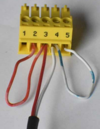
For example, in the picture below we have wired a thermocouple type J into one of the terminals of the ED-593. The black wire is wired into pin 3. The white wire goes into pin 2.
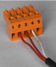
The image below is how we would wire two thermocouples into the terminal. Here we have a type J and a type T.
Below is the terminal block pinouts for the ED-593.
Related FAQs
- What are Inputs and Outputs?
- How do I make my ED devices secure on my Network?
- How do I use C# to communicate with my Remote IO Module?
- How do I send an Xon/Xoff character to control data flow?
- How do I create a windows forms application for Brainboxes Remote IO in C#?
- How do I configure the ASCII settings on my Ethernet IO device?
Related Products
FAQs