What is this FAQ for?
This FAQ will explain how to wire and configure a Brainboxes serial device that features a DB9 serial port, for use in an RS-485 Half-Duplex (HD) configuration.
What is RS-485
RS-485 is one of the three serial standards (RS-232, RS-422 & RS-485) that allows serial devices to communicate data with each other. Under the RS-485 standard, there are two methods of communication, Full-Duplex (FD) and Half-Duplex (HD).
Full-Duplex has 4 serial lines connecting to 2 differential pairs to transmit and also receive data simultaneously. Half-duplex on the other hand has 2 serial lines (Data+ & Data-) which are typically as two terminals to transmit or receive data, however, this cannot be done simultaneously.
What are the advantages of RS-485?
RS-485 supports long-distance communication of up to 1200 meters and can be used in point-to-point or multi-drop bus configurations. This allows multiple devices to be connected on a single bus.
RS-458 is also known for excellent noise immunity making it suitable for industrial environments, process control systems and building automation. RS-485 Modbus cables are also known for their durability.
What are the main limitations with RS-485 wiring?
The RS-485 standard has a defined list of pin functions to be assigned to the serial port, however, it doesn’t strictly enforce that a given pin must always be used for the same function. This leaves manufacturers at their discretion when assigning each pin’s serial functions.
A common problem when wiring RS-485 devices together is that it is not always guaranteed that any two given devices will have the same pinouts. Therefore, an ‘RS-485 cable’ will often need to adapt to different pin arrangements and is unlikely to be ‘standard’ as would be the case with RS232.
In addition to not following a strict pinout arrangement, RS-485 pinout naming conventions can also differ between manufacturers. It is common for RS-485 Full-Duplex assignments to have the function assigned to the pin stated in full. For example, with Brainboxes devices, we use:
- TxD+/- for Transmit+/-
- RxD+/- for Receive+/-
For RS-485 Half-Duplex assignments, the function assigned to a pin and the name provided to that pin’s function can differ from manufacturer to manufacturer. On Brainboxes devices, we use the Data+/- or D+/- naming schemes.
Other manufacturers are at liberty to use the same convention, but can also make use of: TxD+/- & RxD+/-, A/B or 1/2. When using A/B or 1/2 naming conventions, the polarity of the pin isn’t always clearly defined which can lead to further uncertainty when wiring devices together.
How do I wire Brainboxes products for RS485 Half-Duplex?
We often receive requests for how to wire our serial products which feature a DB9 connector in a Half-Duplex configuration. The following will outline the pinouts for Brainboxes RS-485 DB9 serial devices, and how they can be connected both to another Brainboxes serial device, but also to an RS485 device from another manufacturer.
RS-485 Pinouts
All Brainboxes RS-485 devices with a DB9 serial port use the same pinout configuration. Below are the assignments of all 9 pins and their mapping to the physical serial port:
Figure 1: RS-485 pinouts
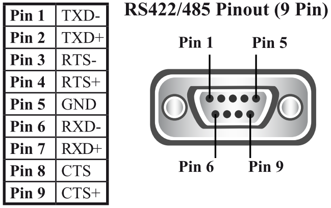
| Pin | Abbreviation | Pin Function |
|---|---|---|
| 1 | TxD- | Transmit Negative |
| 2 | TxD+ | Transmit Positive |
| 3 | RTS- | Request To Send Negative |
| 4 | RTS+ | Request To Send Positive |
| 5 | GND- | Ground |
| 6 | RxD- | Receive Negative |
| 7 | RxD+ | Receive Positive |
| 8 | CTS- | Clear To Send Negative |
| 9 | CTS+ | Clear To Send Positive |
Termination/Biasing Resistors
Before moving onto physical wiring, it is important to first consider and configure the internal serial jumpers. Failure to configure these jumpers correctly can prevent your Brainboxes and external devices from communicating correctly. Most Brainboxes RS-485 devices feature Termination and Biasing resistors on the PCB which can be configured based on the application use case of the device. Some devices have these resistors, however, they’re integrated into the PCB design and do not require configuration.
Termination resistors are used on the end devices of a link to absorb the signal and stop echoes of the data being reflected back onto the data lines. Termination resistors specify if the device is being used in a Full-Duplex or Half-Duplex configuration. Some Brainboxes ES devices feature 4 serial jumpers internally, and others use 5. In principle, both devices will operate in the same manner, although the jumper configurations can differ slightly.
For devices using 4 serial jumpers:
- To configure Full-Duplex communications, the FD jumper must be in the Active position, with the Half-Duplex (HD) jumper in the Park (Inactive) position
- For Half-Duplex communications, the HD jumper must be in the Active position, with the Full-Duplex (FD) jumper being in the Park (Inactive) position. B+/B- Biasing resistors are recommended when the ES device is at the end of an RS485 bus
For devices using 5 serial jumpers:
- To configure Full-Duplex communications, the T jumper must be in the Active position, with both Half-Duplex (HD+ & HD-) jumpers in the Park (Inactive) position.
- For Half-Duplex communications, this can configured differently depending on the users requirements:
-
- For Half-Duplex Point to Point communication, all 5 jumpers must be in the Active position.
- For Half-Duplex Multi-Drop Bus communications, both Half-Duplex (HD+ & HD-) and both Biasing (B+/B-) jumpers must be set to the Active position. The T jumper must be in the Park (Inactive) position.
- For Half-Duplex without biasing, the T and both HD+ & HD- jumpers should be in the Active position. Both B+ & B- jumpers should be in the Park (Inactive) position.


Wiring Examples
Quite often, RS-485 Half-Duplex capable devices feature a 3-Pin connector, with the following pin assignments: Data+, Data- & GND (Ground). The following 3 diagrams (Figure 2 – 4) will illustrate connecting an equivalent 3-Pin connector in the following scenarios:
-
-
- Figure 2 – Connecting a Brainboxes ES-320 with DB9 serial connector to a 3-pin terminal block
- Figure 3 – Connecting a Brainboxes ES-511 with 5-pin terminal block connector, to a 3-pin terminal block
- Figure 4 – Connecting a Brainboxes ES-320 with DB9 serial connector to a DB9 connector from another manufacturer with different pinouts
-
Please note: pinouts may vary from manufacturer to manufacturer. For information on your RS485 devices pinout, please consult the manufacturers datasheet / manual. If you have any uncertainty, please contact [email protected] and we’ll be happy to advise further.
Figure 2: Brainboxes ES-320 to 3-Pin terminal block
This shows a Brainboxes ES-320’s DB9 serial port connector wired into a 3-Pin terminal block.
-
-
- On the ES-320, Pin 1 (TxD+) & Pin 6 (RxD+) are terminated into Pin 2 (D+) of the 3-pin terminal block.
- On the ES-320, Pin 2 (TxD-) & Pin 7 (RxD-) are terminated into Pin 3 (D-) of the 3-pin terminal block.
- On the ES-320, Pin 5 (Ground – GND) is terminated into Pin 1 (GND) of the 3-pin terminal block.
-

Jumper Configurations for Figure 2
Follow the image below, to configure the jumpers for Half-Duplex. The HD, Termination (T) and Biasing (B) jumpers are set to active position.


Figure 3: Brainboxes ES-511 to 3-Pin terminal block
This shows a Brainboxes ES-511’s 5-pin terminal block, wired into a 3-Pin terminal block.
-
-
- On the ES-511, Pin 1 (Ground) is terminated into Pin 1 (GND) of the 3-pin terminal block.
- On the ES-511, Pin 4 (D+) is terminated into Pin 2 (D+) of the 3-pin terminal block.
- On the ES-511, Pin 5 (D-) is terminated into Pin 3 (D-) of the 3-pin terminal block.
-

Jumper Configurations for Figure 3
Follow the image below, to configure the jumpers for Half-duplex. The Full-Duplex jumper is set to park position while the Half-duplex and Biasing jumpers are set to active position.
Figure 4: Brainboxes ES-320 with another manufacturers DB9 Connector
This shows a Brainboxes ES-320’s DB9 serial port connector, wired into another DB9 serial port connector.
-
-
- On the ES-320, Pin 1 (TxD-) is terminated into Pin 8 (RXD-) of the DB9 connector.
- On the ES-320, Pin 6 (RxD-) is terminated into Pin 1 (TxD-) of the DB9 connector.
- On the ES-320, Pin 2 (TxD+) is terminated into Pin 9 (RXD+) of the DB9 connector.
- On the ES-320, Pin 7 (RxD+) is terminated into Pin 2 (TxD+) of the DB9 connector
- On the ES-320, Pin 5 (GND) is terminated into Pin 5 (GND) of the DB9 connector.
-

Jumper Configurations for Figure 4
Follow the image below, to configure the jumpers for half-duplex. The HD, T and B jumpers are all set to an active position.
Please do get in touch with the support team who will be able to assist you further if you require more assistance.
-
- For Half-Duplex communications, this can configured differently depending on the users requirements:
Related FAQs
Related Products
FAQs