FAQs
The Sony 9-Pin Protocol is a 2-way communications protocol for controlling advanced video recorders. Sony introduced the protocol to control reel-to-reel Type C Video Tape Recorders (VTR) and VideoCassette Recorders (VCR). It uses a DB-9 connector with 9 pins, where bidirectional communication takes places over a four wire cable, with accordance to the RS422 Standard.
In the Sony RS422 Protocol, the Controller/Master is defined as the equipment which controls a VTR and the Device/Slave is defined as the equipment which is being controlled. If connecting to a Brainboxes DB9 serial module, it’s important to verify whether your Brainboxes module is a Controller or a Device as the physical wiring configuration will change depending on this.
Below are the pinouts of the Sony RS422 protocol, using a DB9 serial connector:
| Sony RS422 Controller (Master) | Sony RS422 Device (Slave) | ||||||||||||||||||||||||||||||||||||||||||||||||||||||||||||||||||||||||||||||||
|---|---|---|---|---|---|---|---|---|---|---|---|---|---|---|---|---|---|---|---|---|---|---|---|---|---|---|---|---|---|---|---|---|---|---|---|---|---|---|---|---|---|---|---|---|---|---|---|---|---|---|---|---|---|---|---|---|---|---|---|---|---|---|---|---|---|---|---|---|---|---|---|---|---|---|---|---|---|---|---|---|---|
|
|
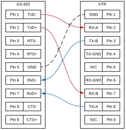
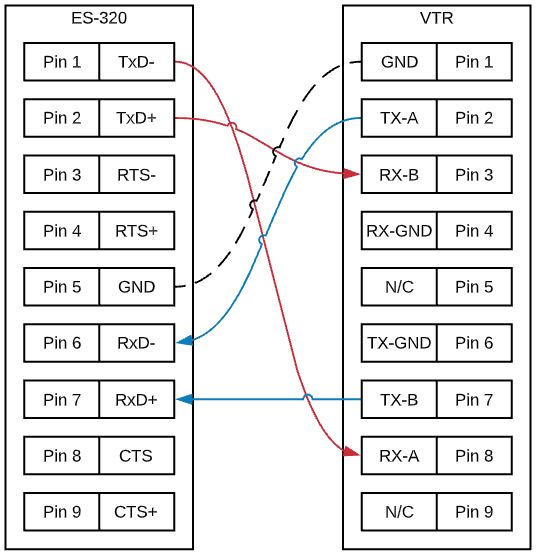
Below are 2 examples of using a Brainboxes ES-320 Ethernet to Serial module with a Sony DB9 VTR. The first example is where the ES-320 is being used as a Controller, with the second using the ES-320 as a Device:
| ES-320 Master |
|---|
 |
| ES-320 Slave |
|---|
 |
FAQs