FAQs
A terminating resistor is simply a resistor placed at the ends of a cable. The value of the terminating resistor is ideally the same value as the characteristic impedance of the cable.
FT (Full Termination Resistors)
Full Termination resistors are normally used in Full Duplex Termination (FT). Full Duplex Termination is a standard of serial communication in which data transmission can occur bidirectionally (transmit and receive in both directions) using separate twisted pairs simultaneously.
The Full Duplex termination jumper setting is normally used when in either Full-Duplex RS-422 or Full-Duplex RS-485 mode and connects a 120 Ohms termination impedance across the ‘Transmit’ and ‘Receive’ wire pairs. Termination resistors are often used to reduce reflections on the network. This problem most commonly occurs with long wires and high baud rates.
Many Talkers – Many Listeners
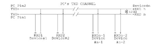
The many talkers, many listeners, Full Duplex system can be used when all the RS-485/RS-422 devices have separate ‘Transmit’ and ‘Receive’ channels. This system is especially useful when there is no flow control available on a PC.
There are many advantages to this system; there is no new communication or software required as the handshaking is performed by the intelligence of the RS-485 devices attached to the PC while still allowing the PC to talk and listen at the same time.
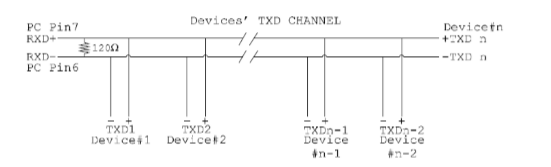
When wired as below, the PC can transmit data at any time and all the RS-485 devices can simultaneously receive it. Only one of the RS-485 devices may talk, i.e. transmit data, at any one time. Each RS-485 device recognises commands and data addressed to it, it only talks when the PC commands it to do so. The other RS485 devices remain in the receive only mode when they are not being addressed, they do not transmit any data at all:
PC’s TXD channel
Device’s TXD channel
HT (Half Termination Resistors)
Half termination resistors are used in Half Duplex Termination(HT). This is another standard of serial communication in which data can be transferred in each direction on the same twisted pair, but not simultaneously (no-multiplexing). The Half-Duplex jumper setting is normally used when in Half-Duplex RS-485 mode and connects a 120 Ohms termination impedance across the ‘Transmit’ and ‘Receive’ wire pairs.
One Talker – Many Listeners
There are different schemes for connecting RS-485 devices depending on the characteristics of the system. In many cases there will be only one device which can transmit data, and all the others simply listen to it – this is shown below. For the talker, the RS-485 TXD GATE jumper should remain in the factory set position, i.e. transmitter is always enabled. There is NO multiplexing of the TXD and RXD lines. Data is only flowing one way, from PC outwards, and is thus a Half-Duplex configuration so only one twisted pair cable is needed:
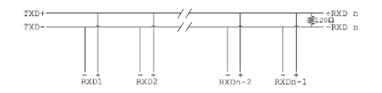
In the above scheme, only one RS-485 device is talking; it transmits data, but does not receive any. The other RS-485 devices are receiving only, they do not transmit any data at all.
Many Talkers – Many Listeners
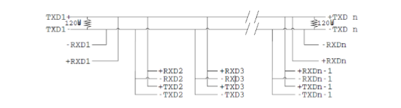
Another popular RS-485 layout is for multiple talkers and multiple listeners – this is shown below. This causes a problem and some method must be implemented to prevent two devices from trying to drive the data lines at the same time. The normal method is to use the RTS line as a talk enable. The RTS line should go true immediately before the data transmission, and go false immediately after the last byte in the stream is sent:
B- & B+ (Bias Resistors)
The final resistors are the biasing resistors (pull-up and pull-down resistors), which are used to configure serial communication for RS-485 or RS-422 standards. They play an integral role in ensuring that the serial communication, in particular the twisted pair, are electrically biased to a controlled voltage while the device is in RS-485 or RS422 mode.
RS-485/RS-422 and a twisted pair are notorious for experiencing interference when the line isn’t being driven (when the line doesn’t have any data passing through it) and quite commonly experiences abnormal data readings which are a result of the interference.
The biasing resistors ensure a constant voltage is sent into the line when data isn’t being transmitted, this prevents floating voltages and background interference (noise) from causing false data readings.
FAQs