FAQs
The BB-400 has 8 I/O lines in total, and they can be found on the following terminal blocks in the corresponding configurations:
- Green terminal: -V, DIO 0, DIO 1, DIO 2 and DIO 3
- Yellow terminal: -V, DIO 4, DIO 5, DIO 6 and DIO 7
Note: if either terminal is being used with a IO line, the -V line (Pin 1 on both terminals) must always be connected.
I/O Line State LEDs
The status for each IO line (Pins 2-5 on both terminals) can be identified on the leading face of the device. The LEDs on the front of the BB-400 relate to the current state of that I/O line. If the voltage is high then the LED is on, and if the voltage is low then the LED will be off.
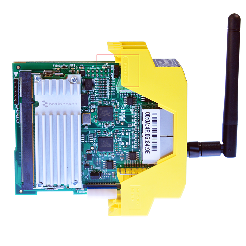
NPN & PNP
The IO lines on the BB-400 can be configured between NPN and PNP modes. NPN inputs pull up to 5V when not driven, and PNP inputs pull to ground when not driven. The NPN/PNP jumper can be found inside the BB-400. If the BB-400 is held with the 2 supercapacitors facing upwards, the jumper is located on the reverse PCB, along one of the edges, highlighted in the image below.
I/O Line Control
To control the I/O lines, an Arduino (ATmega32U4) is used. By default, it is loaded with an I/O server which responds to a command set just like other Brainboxes’ ED devices, over serial from the Raspberry Pi compute module. An important thing to note is that even though the Arduino can be reprogrammed as necessary, the ‘Hardware I/O Line Drivers’ and ‘Pins Exposed’ remain the same.
Logic Levels
The inputs of the ED range of devices, including the BB-400, are compatible with a wide range of devices that can withstand voltages between 0-30V.
For example, consider a LOW signal going HIGH. When the input voltage is at 0V, it is read as a LOW input and given a value of ‘0’. When the input voltage is at 30V, it is read as HIGH and given the value of ‘1’.
But at what point does the value change from 0 to 1, or vice versa, as the voltage changes between 0 and 30V?
The logic levels for the BB-400’s I/O lines are as follows:
- Logic level – 0/LOW : Voltage = 0.0V to 1.0V
- Logic level – 1/HIGH : Voltage = 2.0 to 30.0V
Note: inputs ranging from 1.1V to 1.9V are undefined and may be read as both 0.0V and 1.0V randomly.
The aforementioned logic levels for the input lines are compatible with TTL requirements. TTL is a classic 5V chip-to-chip connection, allowing the ED device to be wired directly to chips on customer’s PCBs.
12V & 24V Digital Inputs
With a transition from 0 to 1 occurring between 1V to 2V, and a maximum input voltage of 30V, ED inputs are perfectly compatible with 12V and 24V devices.
The logic levels for these inputs are as follows:
- Logic level – 0 = 0.0V to +1.0V
- Logic level – 1 = +3.5V to +30.0V
Sinking Outputs
The digital outputs found on the BB-400 are currently ‘Sinking’ outputs, which means they can easily pull the output down to ground, but cannot pull the output up. They act like a switch shorting the output to the ground pin. The maximum current a single output can sink is 0.85 Amp, so large loads can be switched.
Related FAQs
- BB-400 Power Up Process
- How do I configure the BB-400’s Serial Port Jumpers?
- How do I implement PWM (Pulse Width Modulation) functionality on the BB-400?
- How do I mount the BB-400 to a PC?
- How do I use Python to communicate with my Remote IO Module?
- How do I use Python to control the IO over REST on the BB-400
- How do I use Python to control the IO over WebSockets on my BB-400
- How does the BB-400 manage power using the Power Management Unit (PMU)?
- How to communicate using ASCII TCP between the BB-400 and a Linux or Windows system
- How to communicate with the REST API on the BB-400 using cURL commands
- How to communicate with the REST server on the BB-400 through PowerShell on Windows
- What do the BB-400’s LEDs mean?
- What is ‘Edge Computing’?
- What Physical Ports are on the BB-400?
Related Products
FAQs