FAQs
The BB-400 has an array of ports built onto the device which allow it to perform all of the necessary functions required to operate in the next generation factory environment. There are 4 independent Ethernet networks, 2 physical connections via Ethernet but also 2 wireless network connections and 4 number and colour coded terminal blocks. The specification of each port is outlined below.
Ethernet Ports
The BB-400 features a pair of Ethernet ports, each port has a different functionality and allows the device to perform a specific operation. The first Ethernet port is referred to as the ‘Uplink’ port on the front of the device, however, in software (for example the BB_CLI) it is labelled as Eth0. The second Ethernet port is labelled ‘LAN’, (Local Area Network) on the front of the device, however in software it is referred to as Eth1.
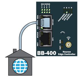
Uplink
The Uplink port is specifically used to connect the BB-400 into a Wide Area Network or WAN, with the most common example of this being the internet. Although it is primarily used for internet connectivity, it can also be used to connect the device into a large private network typically found within a private organisation.
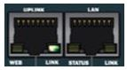
The Uplink port uses Dynamic Host Configuration Protocol or DHCP to retrieve and assign an IP address from the network to itself automatically. The port itself too has features, at the bottom of the port there are 2 LEDs on either side of the connector, each is used to display a message to the user about the ports status. Each LED is labelled and is used to represent a different port state.
The ‘Link’ LED has 3 states: if the LED is on then the device has a network connection, if the LED is off then it doesn’t have a network connection and finally if the LED is flashing then there is activity on that port (i.e. data being transferred).
Additionally, there is a ‘Web’ LED: if the LED is flashing it is checking for an internet connection (it does this every 1 minute) and if the LED is off then the device has no internet connection.
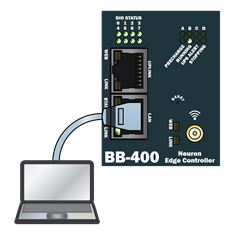
LAN
The second Ethernet port on the BB-400 is referred to as either ‘Eth1’ or ‘LAN’, and like the Uplink port it has a specific role on the device. This port is used to connect the device to a Local Area Network or LAN. A key feature of the BB-400’s LAN port is that when it is connected to a LAN, it automatically takes control of the network and how devices connected to the same network operate.
It is important to note that, when the BB-400 connects to a LAN unlike the Uplink port, the LAN port does not use DHCP to get an IP address for the network. The device has a factory default IP address which is: 192.168.127.1. In addition to this, the BB-400 acts as a firewall, in effect shielding all devices connected to its network from any outside connection. Furthermore to the firewalling, the BB-400 also allows insecure devices to be both physically and logically connected to a WAN.
Much like the Uplink port, the LAN port too has a pair of status LEDs. They are located at the bottom of the port, either side of the connector, and again each represent different states of the device.
The ‘Link’ LED has 3 states: if the LED is on then the BB-400 is connected to a LAN, if the LED is off then it is not connected to a LAN and if the LED is flashing then there is activity in the port (i.e. data being transferred).
Finally, there is the ‘Status’ LED, which has 2 states: if the LED is on then the BB-400 is connected to a 100Mbps network connection and, if the LED is off then the BB-400 is connected to a 10Mbps network connection.
Terminals
A key feature of the BB-400 is its 4 colour-coded terminals with numbered ports: 1 serial, 1 power and 2 digital Inputs/Outputs. Each port on the BB-400 is a different colour which allows the user to easily identify which port is which on the device.
Serial
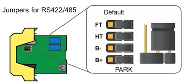
The BB-400 features a configurable serial port, as represented by the grey terminal. The serial port can be reconfigured to best suit the needs of the user, with the functionality of being either a RS232, RS422 or RS485 port. In addition, the terminal allows for a wide range of Baud rates ranging from 300 to 921,600. Finally, there are 4 resistors on the inside of the case which can be changed to configure how the port works. They are labelled as FT, HT, B- and B+.
To find the pinouts for your BB-400’s serial port you can refer to the label on the back of the device, or reference the table below. A more in-depth overview of the BB-400’s serial port including why we chose to implement RS485 can be found in the BB-400 Manual in the Hardware section.
Jumper Configuration for RS422/485:
Pinout configuration:
| Terminal Block | Pin 1 | Pin 2 | Pin 3 | Pin 4 | Pin 5 |
| RS232 | Sig GND | CTS | RxD | RTS | TxD |
| RS422/485 FD | Sig GND | RxD- | RxD+ | TxD+ | TxD- |
| RS485 HD | Sig GND | Data+ | Data- |
Where FD is Full Duplex & HD is Half Duplex.
Power
The BB-400 has a removable power terminal used to supply the device with electricity. As the terminal shows, there are 5 pins (reference pinouts below). The pinouts for this terminal are unique to the BB-400, from left to right, the pins are as follows:
| Terminal Block | Pin 1 | Pin 2 | Pin 3 | Pin 4 | Pin 5 |
| Power (Black) | -V | +V A | +V B | -V | Func GND |

Pin 1 is the first neutral pin, this is where conventionally you would insert the power supplies neutral wire.
Pin 2 is the first live pin, again, this is conventionally where you would insert the power supplies live wire to give the device power.
Now comes the unique feature found on the BB-400, because of its internal components (See ‘Raspberry Pi Considerations’ in the hardware section of the manual for more details on this feature and why its implemented) the BB-400 required a secondary input voltage in order to protect itself from damage should there be a sudden loss of power. The power terminal on the BB-400 features a second power supply.
Pin 3 on the terminal is referenced as Vb, and this is where you can attach a secondary power sources’ live wire, with Pin 4 being the neutral wire. Both neutral wires, Pin 1 and 4 are labelled as –V.
The 5th and final Pin 5 is simply a ground wire as featured on many terminals:
Digital Inputs/Outputs
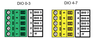
The BB-400 has configurable digital input/output terminals allowing the device to be set in a number of different ways. Again, both terminals are numbered and colour-coded, and their pinouts are as follows:
| Terminal Block | Pin 1 | Pin 2 | Pin 3 | Pin 4 | Pin 5 |
| Green Terminal | -V | DIO 0 | DIO 1 | DIO 2 | DIO 3 |
| Yellow Terminal | -V | DIO 4 | DIO 5 | DIO 6 | DIO 7 |
Please Note: When any of the BB-400’s DIO ports are in use, the -V or Ground pin (Pin 1 on both terminals) must always be connected.
Related FAQs
Related Products
FAQs