How do I control the IO lines through the Web Admin interface?

FAQs

The BB-400 contains 8 ports that are individually selectable as inputs or outputs, located on the green and yellow terminals. It is possible to control the IO lines via the Web Admin interface and this FAQ will discuss the different configurations available and their details. For more information regarding the DIO lines please refer to the DIO lines FAQ.

Web admin page
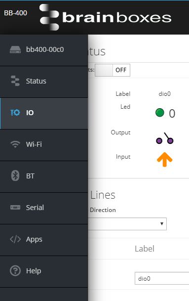
After logging into the BB-400 cockpit page, the IO status can be found by clicking on the IO status page on the sidebar:

files/pages/support/faqs/bb-400-faqs/how-do-i-control-the-io-lines-through-the-web-admin-interface-io-webpage.png

IO Status

The top of the page shows the current IO status of the device:

files/pages/support/faqs/bb-400-faqs/how-do-i-control-the-io-lines-through-the-web-admin-interface-initial-page.png

It is possible to adjust the outputs by changing the clickable outputs option to on:

files/pages/support/faqs/bb-400-faqs/how-do-i-control-the-io-lines-through-the-web-admin-interface-clickable-buttons-on.png

Clicking on the output will change the configuration to on or off, e.g. turning all of the outputs off:

files/pages/support/faqs/bb-400-faqs/how-do-i-control-the-io-lines-through-the-web-admin-interface-all-outputs-off.png

or changing some of the outputs to on and some to off:

files/pages/support/faqs/bb-400-faqs/how-do-i-control-the-io-lines-through-the-web-admin-interface-outputs-on-and-off.png

LEDs

There are 8 LEDs on the front of the BB-400, each corresponding to a DIO line, as shown by the image below:
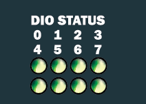
files/pages/support/faqs/bb-400-faqs/bb-400-leds/DIOstatus_LEDs.png

The LEDs will respond to the webpage change in IO status.

How the NPN/PNP jumper affects the LEDs

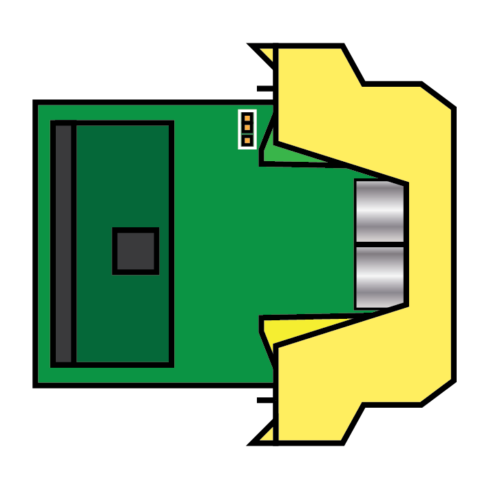
The status of the DIO lines can be adjusted between NPN/PNP mode, and the jumper that controls this can be found inside the BB-400, highlighted below:
files/pages/support/faqs/bb-400-faqs/how-do-i-control-the-io-lines-through-the-web-admin-interface-npn-pnp-jumper.png

Remember to allow your device to fully power down before adjusting the jumper.

NPN mode

When in NPN mode the inputs are pulled up to +5V and the table below represents the different configurations for the output and input, and how this affects the status of the LED.
Output Input LED
Open Low Off
Open High On
Closed Low Off
Closed High Off
The table shows that the only situation in which an LED is on, is if the output is open and the input is high:
files/pages/support/faqs/bb-400-faqs/how-do-i-control-the-io-lines-through-the-web-admin-interface-when-led-on.png

PNP mode

When in PNP mode the inputs are pulled down to ground. This means that regardless of the output status, as the inputs are not high, the LEDs do not switch on:
files/pages/support/faqs/bb-400-faqs/how-do-i-control-the-io-lines-through-the-web-admin-interface-pnp-status.png

files/pages/support/faqs/bb-400-faqs/how-do-i-control-the-io-lines-through-the-web-admin-interface-pnp-output-adjusted.png

Configuring IO Lines

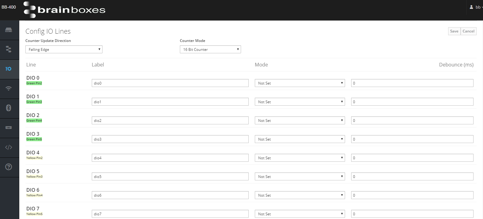
The next section of the webpage, “Config IO Lines”, deals with configuring the IO lines and is described in further detail below:
files/pages/support/faqs/bb-400-faqs/how-do-i-control-the-io-lines-through-the-web-admin-interface-config-io-lines.png

Counter Update Direction

The counter update direction can be set so the signal transition is either:
  • falling edge, moves from high to low
  • rising edge, moves from low to high

Counter Mode

The counter can be set to either 16 bit (65335 count) or 32 bit (4.2 billion count) mode. The counter values persist over power-off periods.

Line

The line column represents the hardware configuration of the IO lines. On the BB-400 the IO lines can be found on the green or the yellow terminal blocks. The green pins correspond to DIO 0 – DIO 3, and the yellow pins correspond to DIO 4 – DIO 7.

It should be noted that pin 1 on both terminal blocks is the -V line, and should always be connected if either terminal is used with a DIO line.

Label

Here, the name of each IO line can be changed if required. Please note the webpage will not allow you to enter any invalid characters, such as, but not limited to: “*(^%”!@$”.

Mode

There are 4 options for the mode: input, output, unused and not set.
files/pages/support/faqs/bb-400-faqs/how-do-i-control-the-io-lines-through-the-web-admin-interface-changing-modes.pngWhen the IO status is changed to an input or a output, the line behaves in that mode only. Changing a single or multiple line(s) to unused means the line cannot be adjusted in any way and remains not in use.
It is also possible to set a line to the “not set” option, in this mode the status of the IO line can change between an input or an output.

Debounce

It is possible to set a debounce value, that is the time the digital signal can’t be registered, with a maximum value of 4000 ms.

The debounce value cannot be adjusted if a IO line’s mode has been changed to either ‘Output’ or ‘Unused’.


FAQs