FAQs
The ED-549 offers 8 analogue inputs. You can find the location of the inputs from the pin out diagram by matching the colours and numbers. Note each input has two pins -(negative) and +(positive) and the first input is labelled AIn 0 (zero):
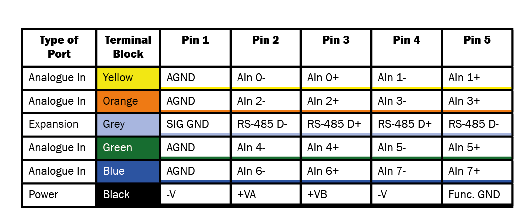
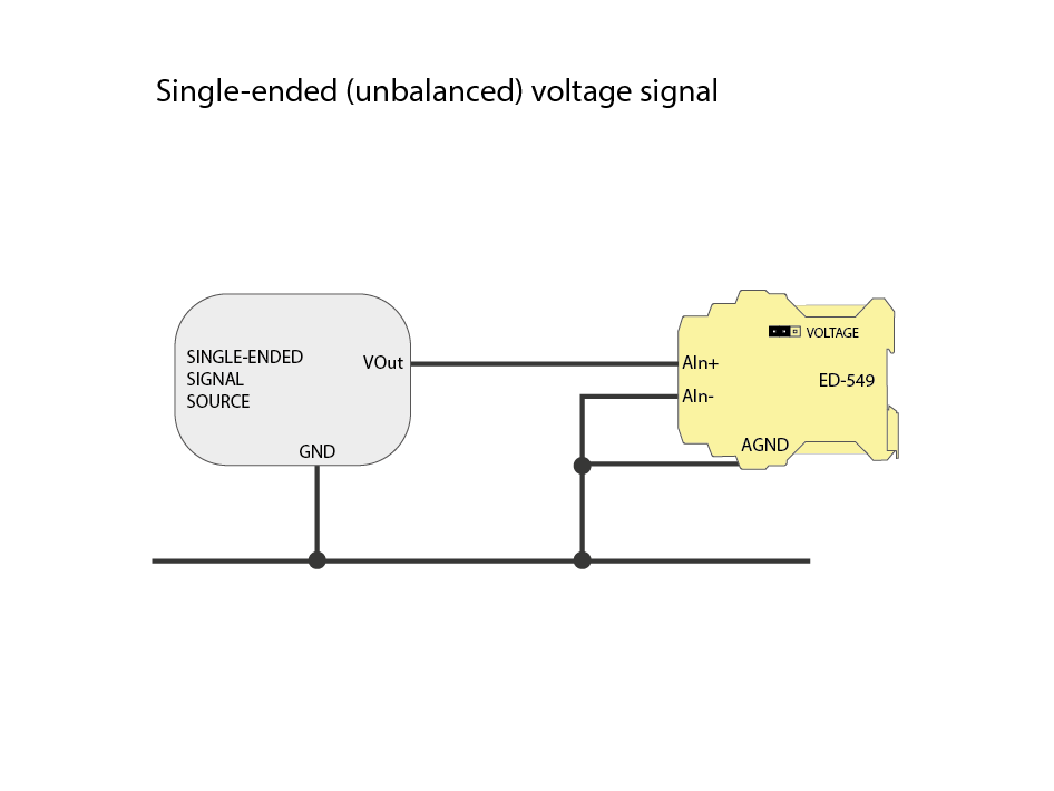
Next you need to decide which wiring option is best for your application. There are three main configurations, current loop signal, differential (balanced) voltage signal and single-ended (unbalanced) voltage signal.
The current loop signal option is a typical circuit for 4-20 mA devices. The circuit can be used to power some transducers, for example a temperature or pressure sensor, providing a convenient and simple installation for many common sensors.
Single-ended signals with their common ground connection are susceptible to noise. Differential signals however measure the voltage between two inputs enabling the noise to be cancelled out. When using differential signals you need to be careful not to ignore a connection to ground, as without this reference
the signals ‘float’.
In general, differential wiring is often a better choice over single-ended because of the noise reduction allowing connection over greater distance, clarity for small signals or high resistance sensors, and connections between signals that have different grounds.
Typical examples:
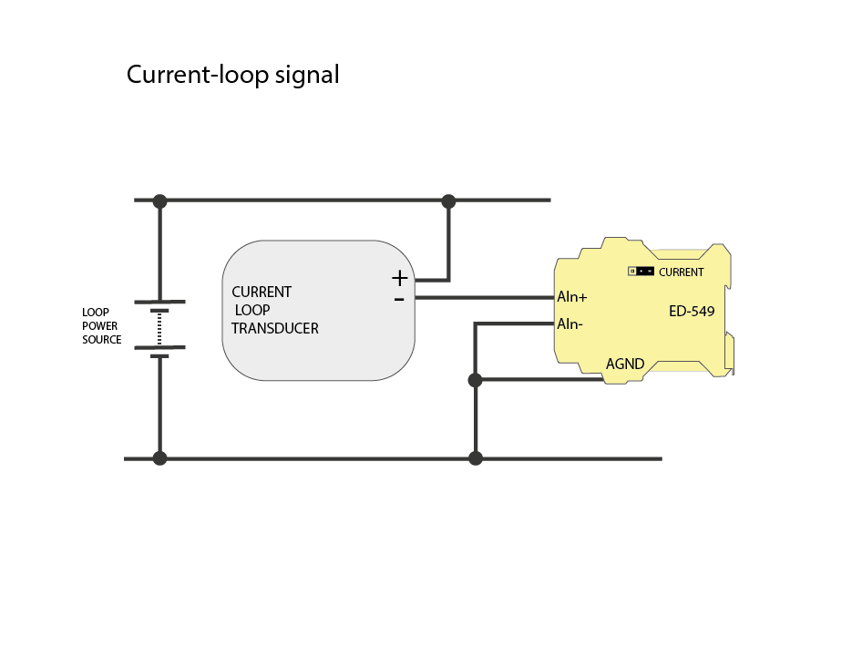
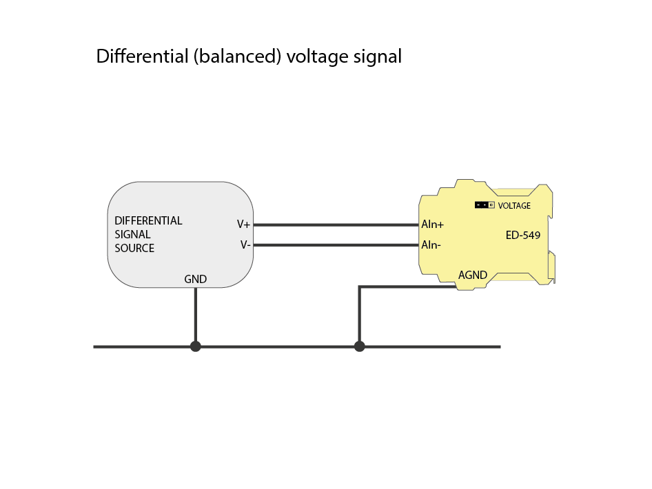
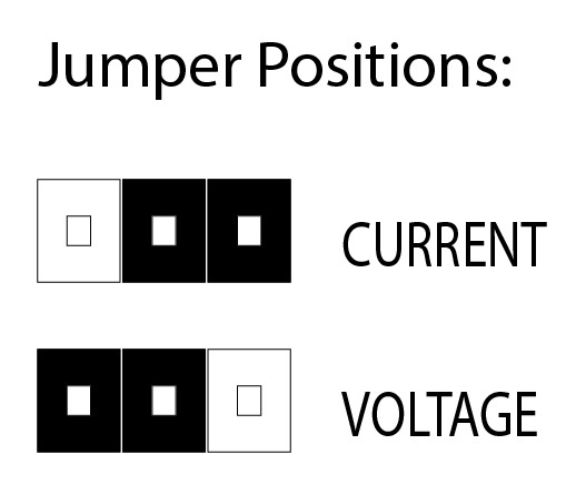
Note the position of the jumpers for voltage or current. To set the jumpers you will need to open the case by depressing the catches at the top and bottom, (a flat head screw driver is ideal for this). The jumper positions are labelled on the board to help you get the right orientation. Once the jumpers are set to the desired position slide the board back into the body of the case and press till the catches click.
